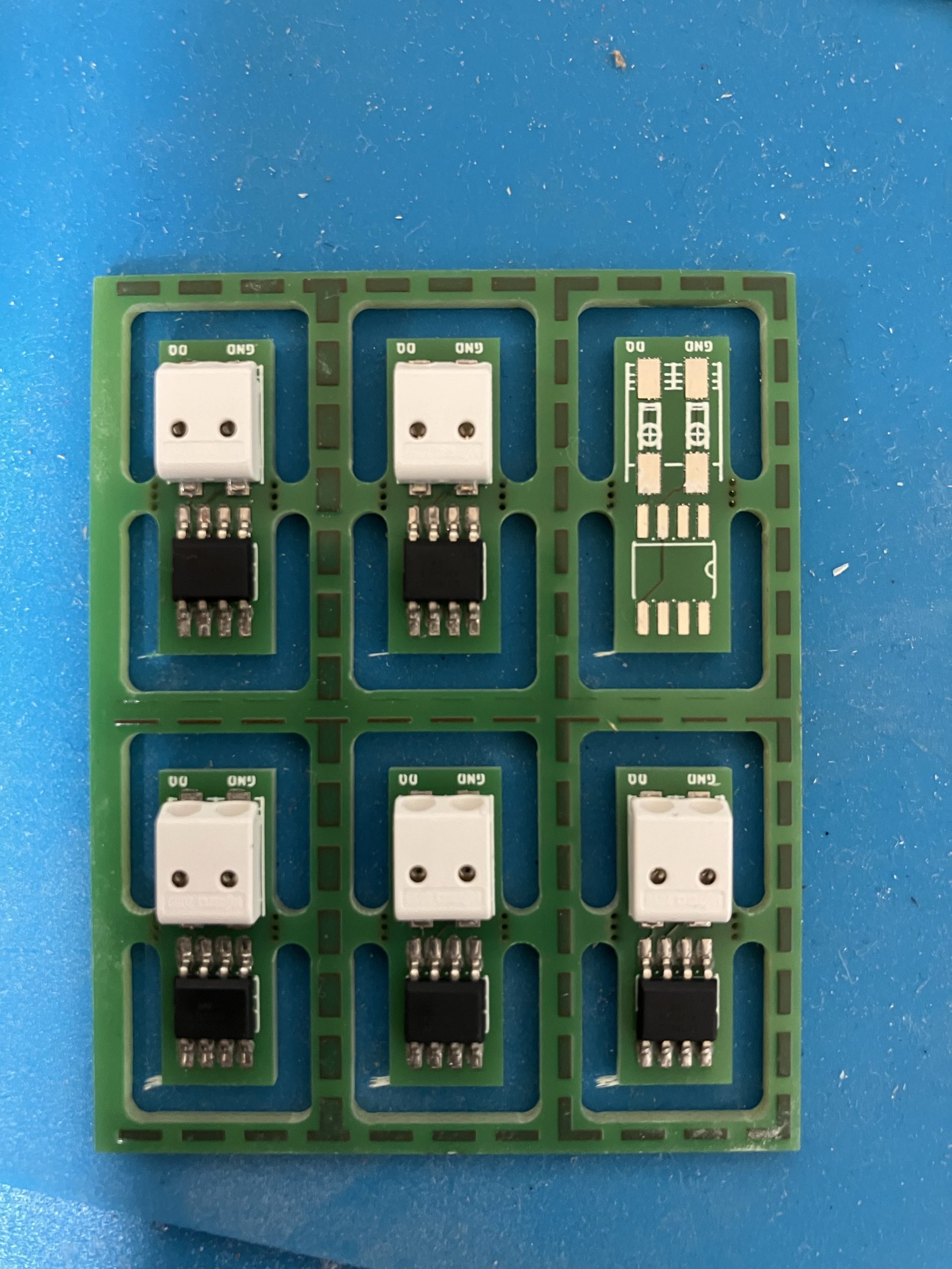
After creating the first few temperature sensors the PCB has been updated. It’s smaller now. Soldering went smoothly. The fact that the PCBs came in groups of 6 made applying the solder paste much faster. After soldering the PCBs did not look very nice. But after measuring all were as expected and the question is whether to clean the PCBs would help to make sure the the remaining dirt does not cause long term problems. Unfortunately an off by one issue appeared.
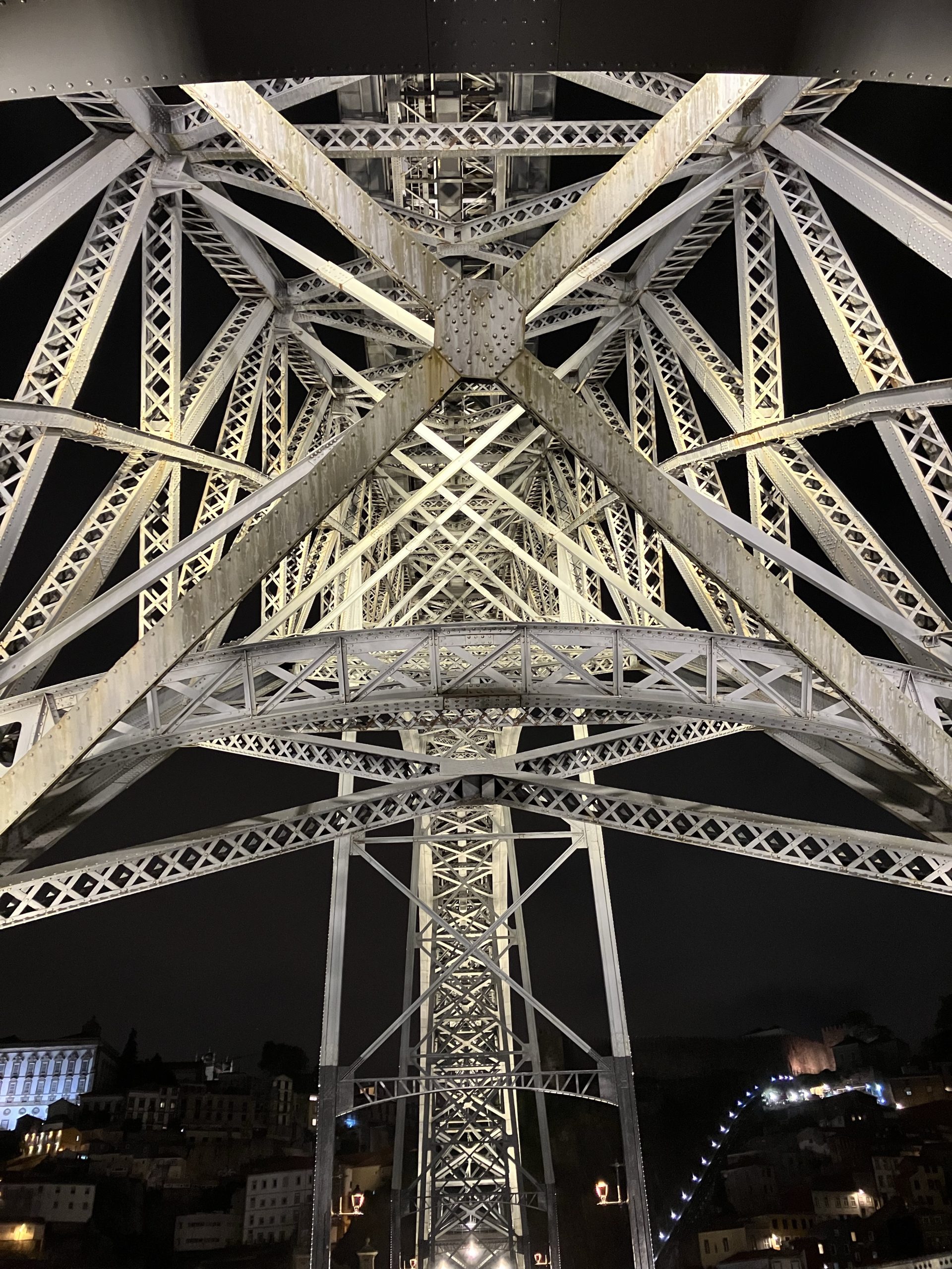
A little bit up the river from our house is the Dom Luís I bridge. Even though Eiffel’s design was rejected his former partner Théophile_Seyrig was awarded with the project. So the similarity is not purely accidential.
Tarballs for this new release are available on the Download page and updated Ubuntu packages can be found in the terminatorX PPA. Changes from 4.1.0 include:
A new sinc based interpolator that improves resampling quality quite a bit, if you prefer the old aliasing artifacts a new configuration option allows to switch back to the old linear interpolation.
Updated the artwork a bit with a “Tux under threat” theme (yes, that is another Public Enemy reference) – the source code based label was really dated.
Before I proceed to manufacture the PCBs for the home automation I decided to invest in a solder plate and try a very small project: Temperature sensors that consists of a DS18B20 1-wire temperature sensor and a 2-pin SMD push connector.
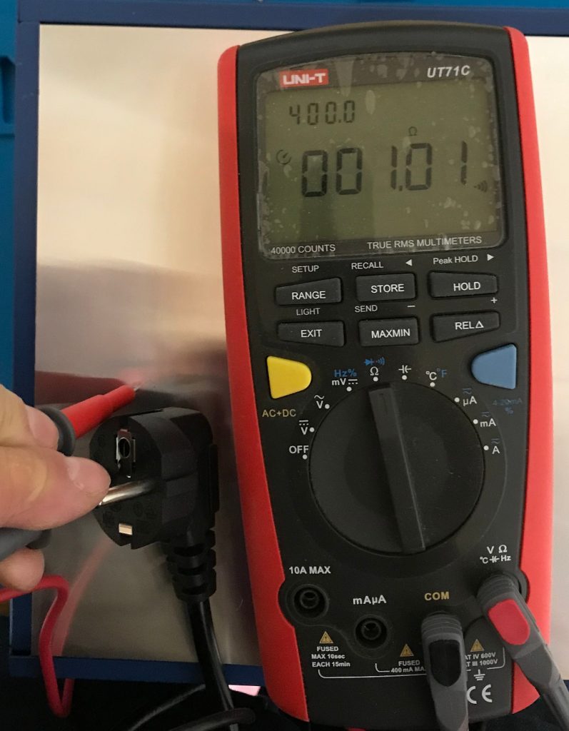
First step was to make sure that the solder plate is actually grounded properly.
1 Ohm is acceptable
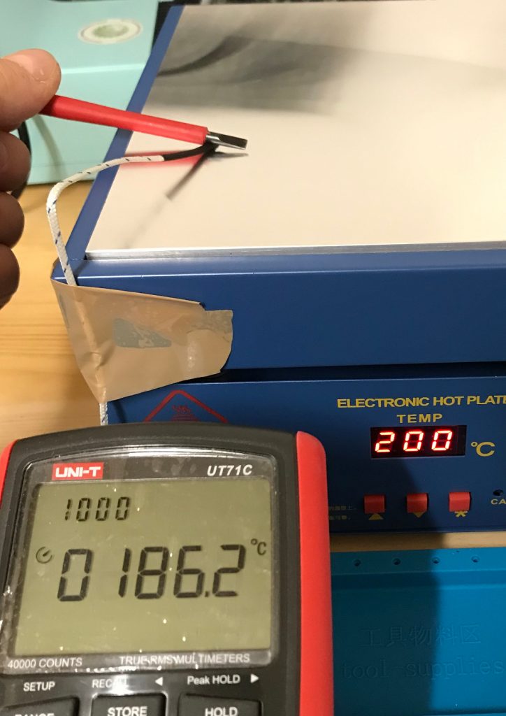
After that a layman’s temperature calibration run. Comparing the temperature using my multi-meter’s temperature probe and the internally measured value of the solder plate.
Close enough
The PCBs were designed with eagle and manufactured by AISLER. They look good, were reasonably priced and came with a stencil.
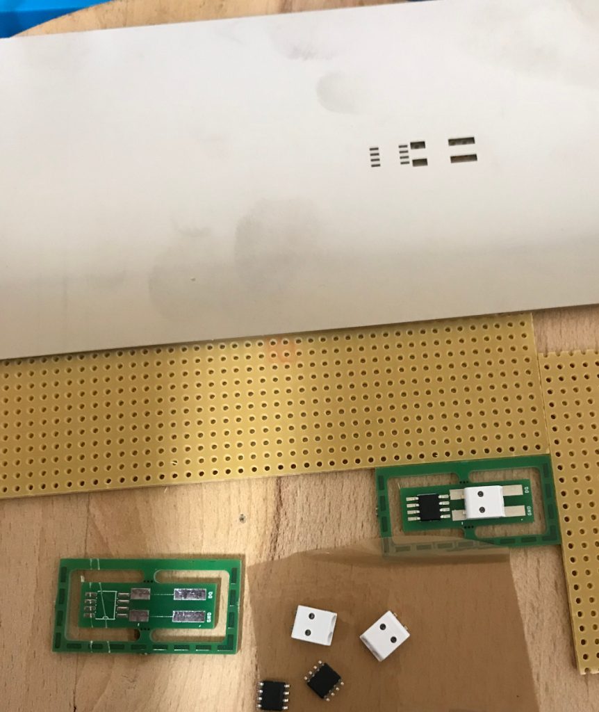
On to solder paste application. The setup consists of a piece of wood with two pieces of PCB with the same thickness as the target PCB and the stencil taped in place after alignment. You can see in the image that the stencil is far from perfectly parallel to the hole line. The effect of slightly offsetting the solder paste will be visible soon.
Solder paste application setup on a wooden board and a dry fit of the parts
Flipped the stencil over and put a drop of solder paste.
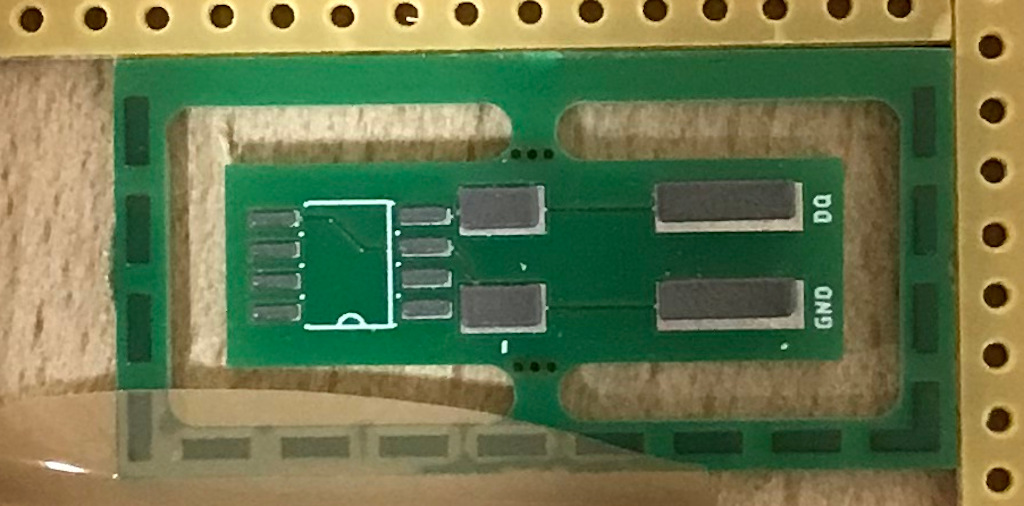
Before application of the solder paste
Using a metal scraper to apply.
Solder paste applied.
The above mentioned error is visible, but I hope that it does not cause issues later and the amount of solder paste looks good. Next step is placing the parts.
Using tweezers to place the parts
Now let’s heat it up. Since I’m using the solder plate for the first time I did not take enough pictures to capture the whole reflow solder profile. I’ve set the temperatures manually and have waited using a timer. The relatively slow solder plate ensures the ramping is not too fast. The cooling after reaching maximum heat is a little bit slow, but will be improved once I’ve the ventilation in place that is definitely required for larger projects. The fan is already in place, so I’ll have to add an enclosure only.
Solder paste shortly after it started melting
Wait until it’s cooled.
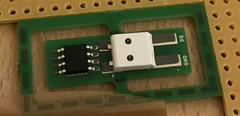
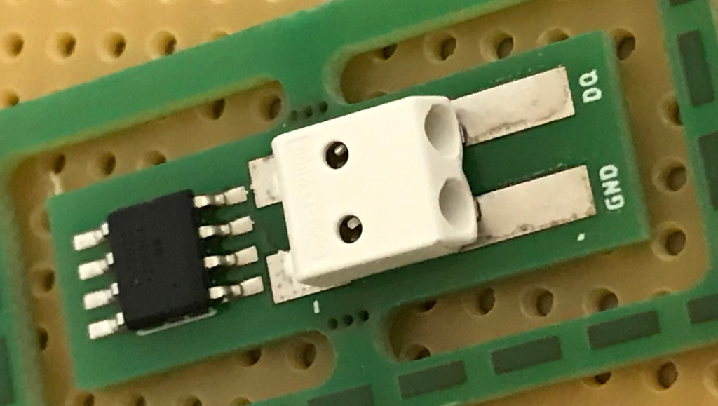
The the solder joints look acceptable
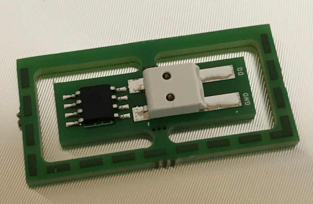
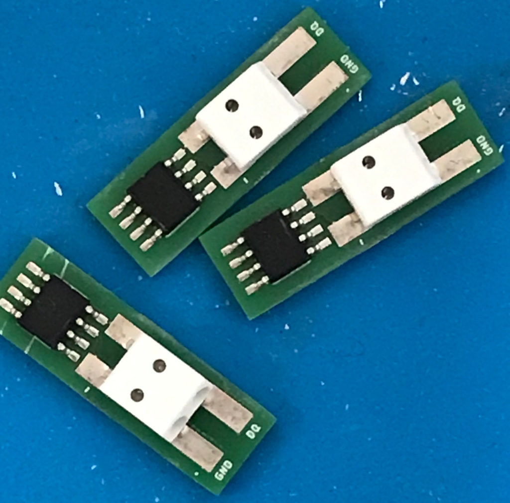
Considering the fact that the connector does not match 100% with the footprint (the 8D process will show what went wrong) the solder joint is acceptable. The temperature sensor looks good to me. (Feedback welcome). After the first one was successful I finished the series by soldering the remaining 2 parts.
The complete series of 3 parts is finished
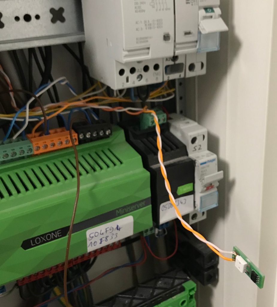
PCBs routed and sanded. I did a quick electrical test. With only 2 connections it could easily be done with the multi-meter. So the next step was to integrate the new sensor in the existing Loxone home automation system.
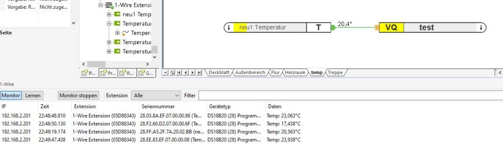
The newly produced sensor is connected to the live system
The sensor was successfully detected and provided a reasonable temperature.
The software displays a reasonable temperature value
In addition I’ve placed one of the sensors outside and it also show values that made sense.
I’ll order more PCBs and run a second batch and after that I’ll be out of excuses for producing the bigger PCBs for my light switches.
We’ve decided to retire the bugzilla instance at lisas.de – so in order to file new bug reports or feature requests for terminatorX please use github’s issue tracker instead or file a pull request.
Finally, I had the chance to polish the source code a bit for releasability, after having a bunch of smaller improvements sitting in the git tree for quite a while.
Rearrange the effect processing order through drag’n’drop (click for full-size)
Release 4.1.0 brings:
Turntable colors to quickly find the right controls/or audio data
Effect queues can now be rearranged using drag’n’drop
Old icons have been replaced with stock versions
Workaround for duplicated events in wrap pointer mode as under some conditions X11 may generate motion events when warping
I finally got around to looking into why my rsync automation fails with my new Lineage OS 17.1 device. The old instructions worked like charm. Sshd will start, but the shell user will receive a permission denied after successful authentication.
It turns out that sshd is unhappy with the file ownership or modes for /data. Now I didn’t want to mess with those nor did I want to move the ssh directory to another place so I cheated and told sshd to relax by adding:
StrictModes no
to sshd_config. Probably sshd dislikes that /data is owned by system and not shell nor root – allowing the system user to erase the ssh directory. Seems like one security concept is ruining another…