Watchdog for the raspberry pi

As mentioned by Alex the link was down. Two things happened:

  1. The raspberry pi was not running anymore.
  2. The Internet connection was down.

For the second problem I don’t have a solution yet. For the not running raspberry pi there might be one:

The internal watchdog of the raspberry pi. It can be activated by loading the module, making sure it gets reloaded after a restart and installing the triggering software.

$ sudo modprobe bcm2708_wdog
$ echo "bcm2708_wdog" | sudo tee -a /etc/modules
$ sudo apt-get install watchdog

Configuration happens in the file

/etc/watchdog.conf

by uncommenting the following lines:

watchdog-device        = /dev/watchdog
max-load-1             = 24

This is a very basic configuration and it will restart the raspberry pi in case the load is above 24 for a 1 minute interval.

Activation of the demon can be done like this:

$ sudo service watchdog start

Specific in my case is the additional option to check whether the file, that was not working as mentioned above, is written to on a regular basis. This can be achieved by adding the following lines in the configuration:

file = /data/solar/solar.touch.start
change = 300
file = /data/solar/solar.touch.end
change = 600

Each “file” entry specifies a file that will be checked by the watchdog whether it’s been touched and the “change” entry specifies the time that the file can stay untouched before the watchdog will not be triggered any more and by that lead to a system reset. The first file is touched at the start of the script, the second one at the end. So in case the script for updating the yield data is not called any more the system will be reset after 5 minutes. If the script is started, but does not finish properly it’ll be reset after 10 minutes.

Time will tell how reliable the watchdog is.
IGEL W running

After not even switching my IGEL for a very long time I finally got it running using thinstation and the service tsomatic to build the files instead of doing it on my own.  Unfortunately it takes longer to start and only run ssh than the desktop PC I own. Initially the idea was to have a machine that runs directly after switching on.  But it’s running and not used only as a display support any more.

New Toy

Since my boss told me to reduce my overtime I’ve ordered a new toy to compensate the lack of work.
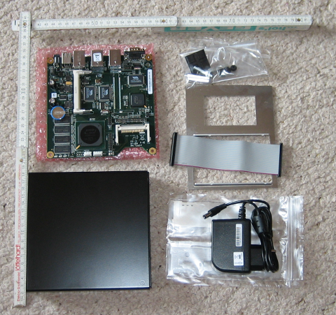
Alix unpacked
Currently I’m installing the system based on this description. Main idea is to get rid of the loud, big and of course power consuming solution I currently use as internet gateway and print server.

Saving the planet

I’ve moved my printer to another room. Now it’s connected to my continuously running computer. But it’s constantly connected to power and is not really switching off. So I was searching for a solution to switch it of automatically. Using a µC would be nice, but the idea a the moment is to use a USB->serial converter and us the status pin RTS to switch a solid state relay. Today I’ve successfully tested the setup. First I tried with python, which in general is able to set the status of that pin, but unfortunately python is too “high”. During initialization and termination RTS is touched. And I don’t want to “shock” my printer with short switching pulses. But I’ve found this C-code. This allows to keep the state of the pin after termination of the program. This little piece of code exactly does what I need. I’ve added a diode before connecting RTS to the solid state relay to make sure that the relay does not see a negative voltage. I can not yet post a picture of that because my prototype is highly dangerous and I don’t want to provide any examples of dangerous 230V wiring on the net.

The next step will be to set up a cups backend that switches on and off the relay.

Putting things together

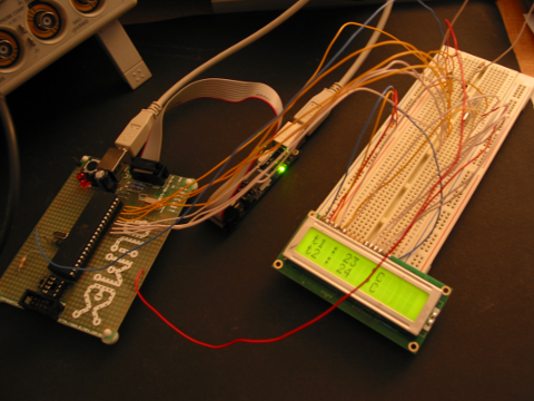
Since I’m on holiday I have more time to play with the µC. I’ve now got a 2X16 character display running and I can read temperature from the small one-wire sensors. So I’ve put that together and created a thermometer.

one-wire temperature sensors  and LCD

The sensors are the small barely visible black dots on the upper part of the breadboard. The oscilloscope visible on the left I’ve taken with me from office during Christmas holiday since I can’t afford such a thing.

next steps

Now that the prototype is running it’s time to move on to “series” production. The files of the first version are here.
So a PCB has to be designed and the parts have to be selected and tested. Selecting the parts is not that difficult, but designing a PCB is not that easy since I don’t have any experience. In addition it looks like the old days are finally over. It’s becoming more and more difficult to get non-SMD-parts.
Btw: I’ve updated the pictures. The red background was a little bit too much and had to be changed to black.
Question: Does anybody have a good idea how to take picture to show that the dimming is working?

First Result

Yesterday evening the first real result was visible. Reception of DMX data and output of PWM on 8 channels is working now.

At the moment it’s only a development board.

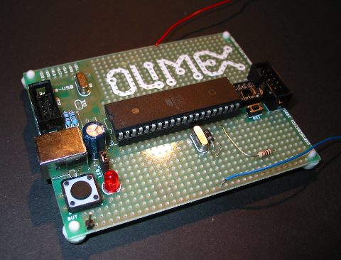
prototype board

All external parts are attached via loooong cables to other hardware.

A PCB Design is ongoing, but not all the details are yet clear for series production.

OKOK, that was maybe a little bit to short. First of all:

DMX: a strange protocol, that looks like it was intended to keep amateurs from building their own devices by adding a protocol error as start signal. But with todays µCs is possible, even though it’s a little bit ugly.

In my setup there is a light control desk which is the sender. So I only care about receiving at the moment.

The received 8 byte are saved in the µC and are the input data for the PWM generator.

Th PWM signal is used for PFC.

An external circuitry is used to detect the zero crossing of the 230V AC and based on the received DMX data triacs can be started.

Now that the basic functionality is working I can add service functions and error detection.

USBprog

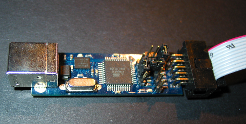
USPprog (available here) is a very useful tool. I mainly use it as a AVRISP mk2 clone. This is done by flashing an AVRISP mk2 emulation firmware in the µC of the USBprog. Tools for doing that are available for the command line and also as GUI. I’ve ordered the parts together with some ATMega32 µCs and a prototype board. Since the USBprog consists of very few parts it can be easily soldered even by not so experienced users. The result looks like this:

The difficult part is to flash the boot loader SW on it. It’s a chicken/egg problem. I want to flash a SW on a µC that I want to use for flashing a µC. But with an old PC that has a parallel port it can be done.
After that I had a working USBprog. On the right you can see the USB port and on the left the cable used to connect to the µC.

Justification

Having a complete PC is a good thing, but for controlling small things like a light it’s way too big and expensive, so I’ve decided to use smaller processors for that. After some research I ended up with the AVR micro controllers made by Atmel. They are easily available and affordabel  and what is even more important: An open source toolchain consisting of avr-gcc and avr-libc exists and even the hardware I’ll be using for programming the µCs is open source: USBprog.