Before I proceed to manufacture the PCBs for the home automation I decided to invest in a solder plate and try a very small project: Temperature sensors that consists of a DS18B20 1-wire temperature sensor and a 2-pin SMD push connector.
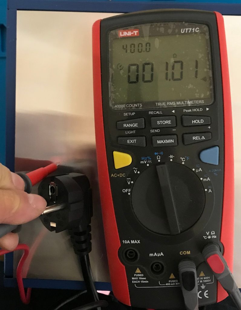
First step was to make sure that the solder plate is actually grounded properly.
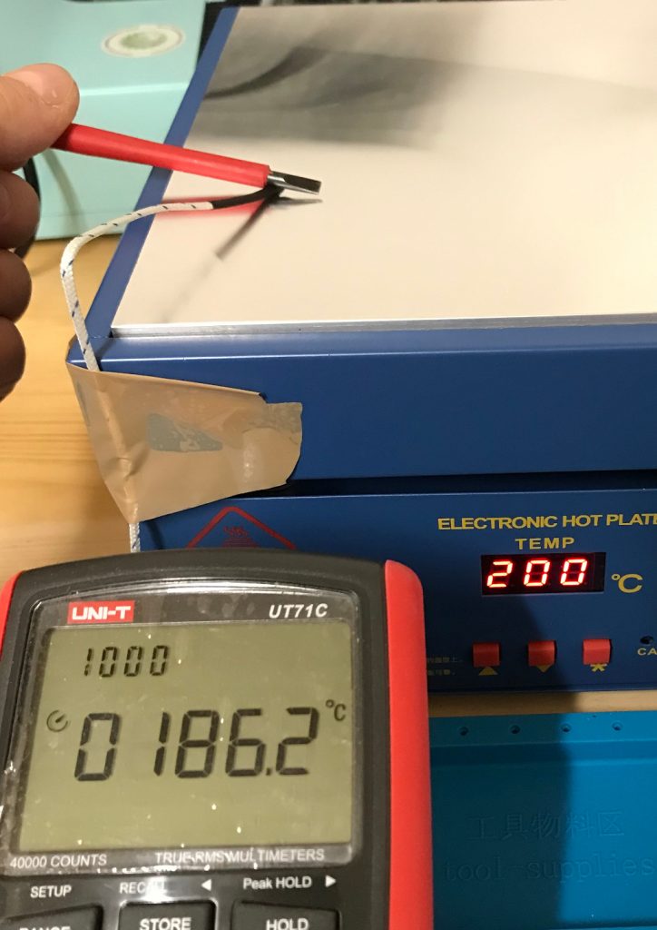
After that a layman’s temperature calibration run. Comparing the temperature using my multi-meter’s temperature probe and the internally measured value of the solder plate.
The PCBs were designed with eagle and manufactured by AISLER. They look good, were reasonably priced and came with a stencil.
On to solder paste application. The setup consists of a piece of wood with two pieces of PCB with the same thickness as the target PCB and the stencil taped in place after alignment. You can see in the image that the stencil is far from perfectly parallel to the hole line. The effect of slightly offsetting the solder paste will be visible soon.
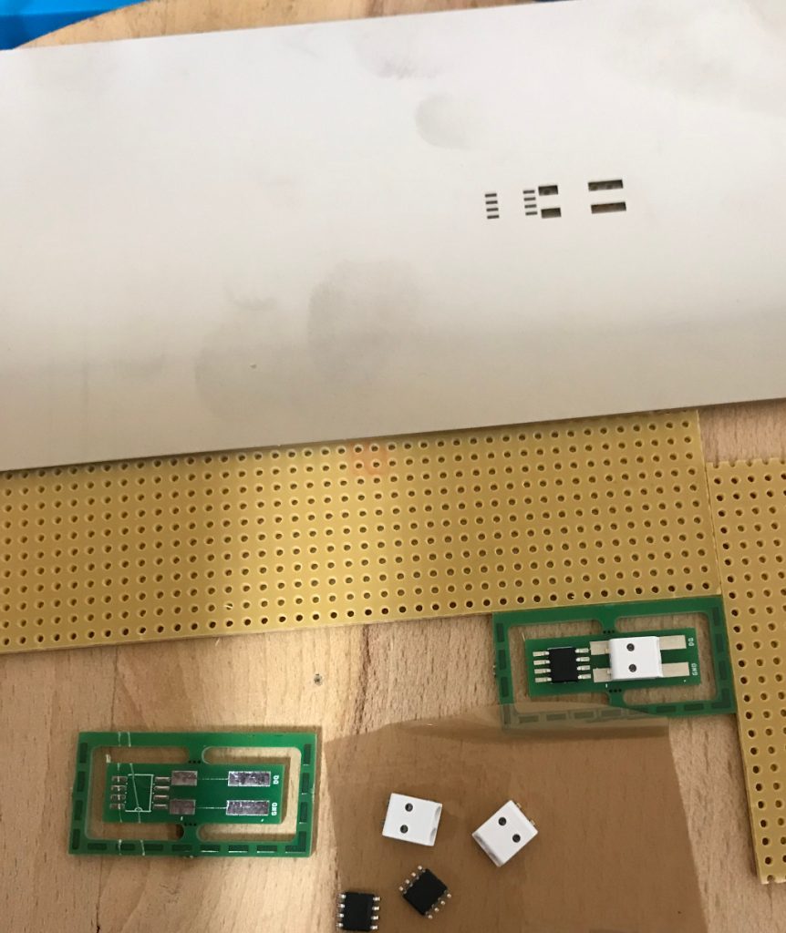
Flipped the stencil over and put a drop of solder paste.
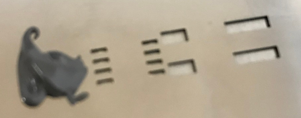
Using a metal scraper to apply.
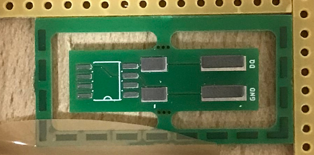
The above mentioned error is visible, but I hope that it does not cause issues later and the amount of solder paste looks good. Next step is placing the parts.
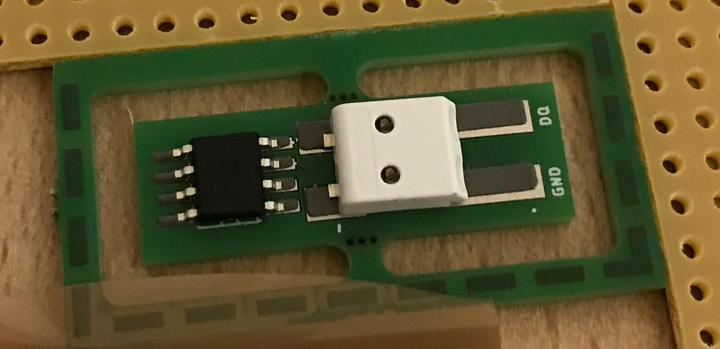
Now let’s heat it up. Since I’m using the solder plate for the first time I did not take enough pictures to capture the whole reflow solder profile. I’ve set the temperatures manually and have waited using a timer. The relatively slow solder plate ensures the ramping is not too fast. The cooling after reaching maximum heat is a little bit slow, but will be improved once I’ve the ventilation in place that is definitely required for larger projects. The fan is already in place, so I’ll have to add an enclosure only.
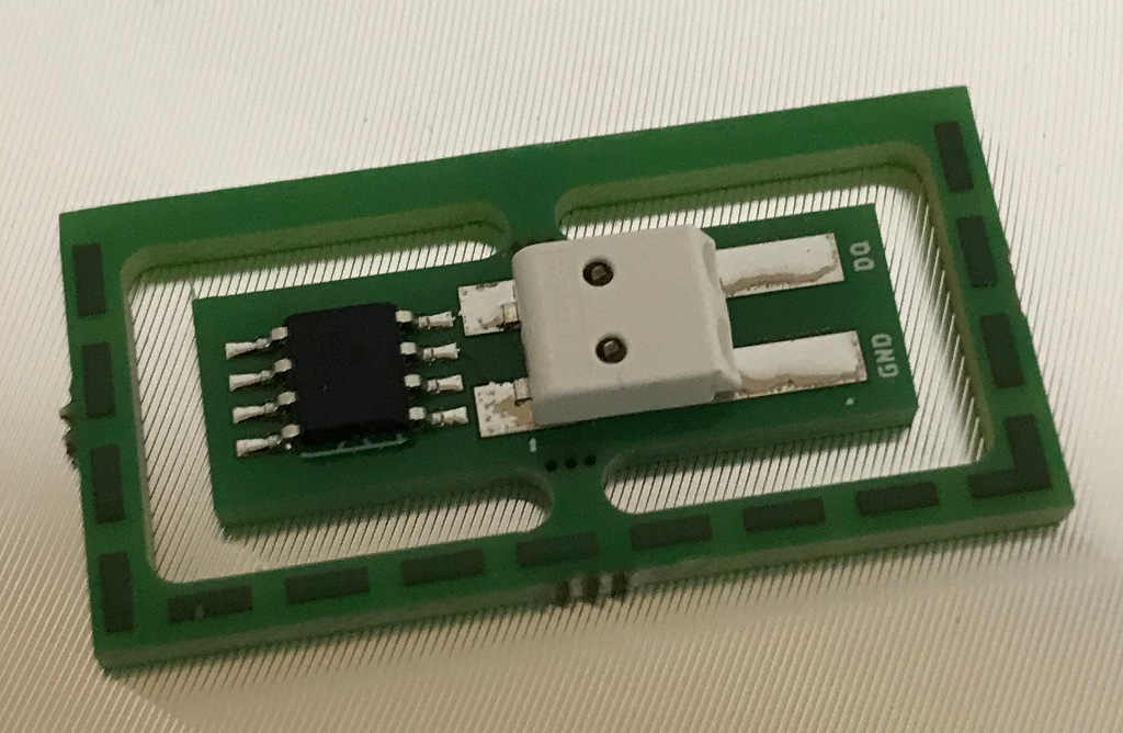
Wait until it’s cooled.
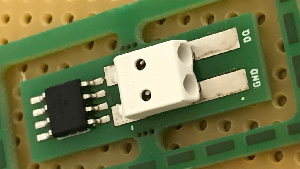
Considering the fact that the connector does not match 100% with the footprint (the 8D process will show what went wrong) the solder joint is acceptable. The temperature sensor looks good to me. (Feedback welcome). After the first one was successful I finished the series by soldering the remaining 2 parts.
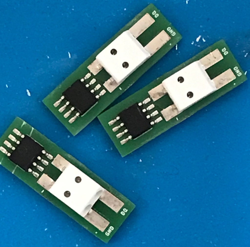
PCBs routed and sanded. I did a quick electrical test. With only 2 connections it could easily be done with the multi-meter. So the next step was to integrate the new sensor in the existing Loxone home automation system.
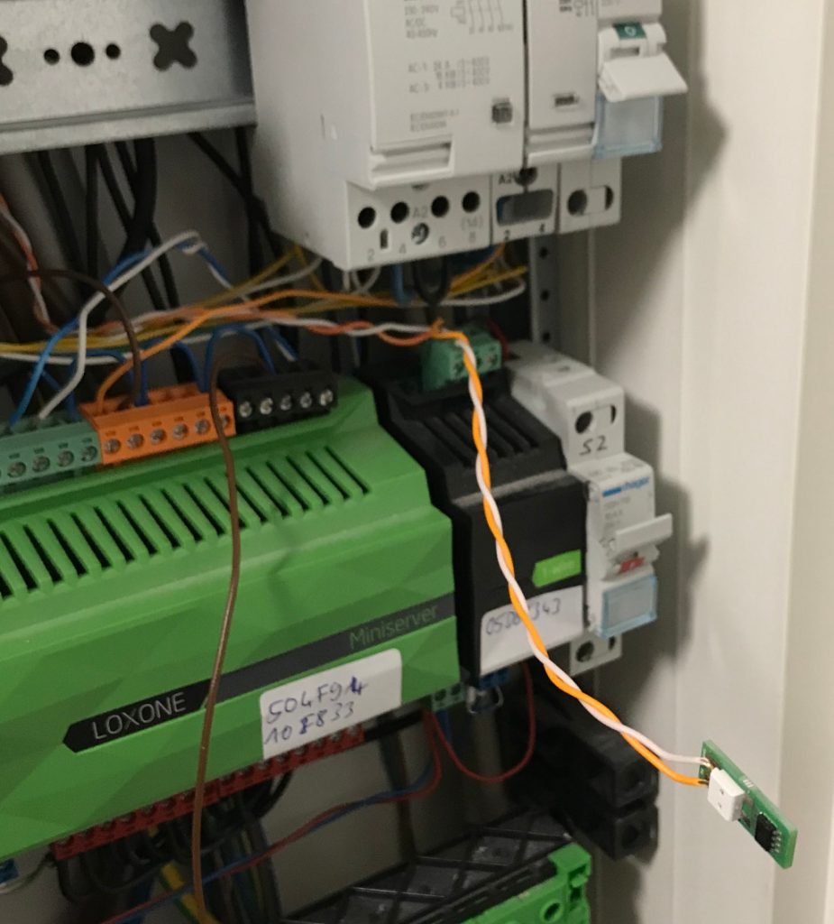
The sensor was successfully detected and provided a reasonable temperature.

In addition I’ve placed one of the sensors outside and it also show values that made sense.
I’ll order more PCBs and run a second batch and after that I’ll be out of excuses for producing the bigger PCBs for my light switches.