Soldering temperature sensors

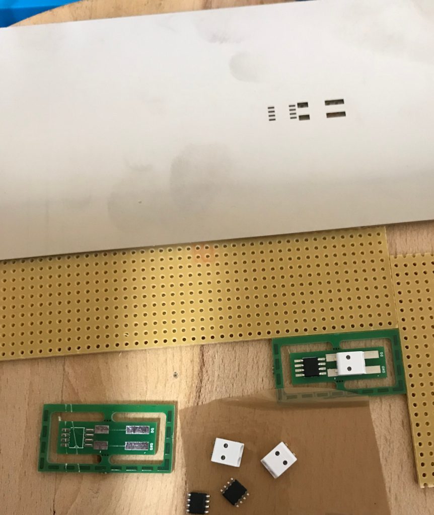
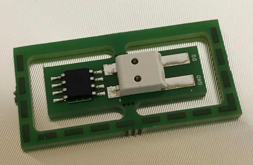
Before I proceed to manufacture the PCBs for the home automation I decided to invest in a solder plate and try a very small project: Temperature sensors that consists of a DS18B20 1-wire temperature sensor and a 2-pin SMD push connector.

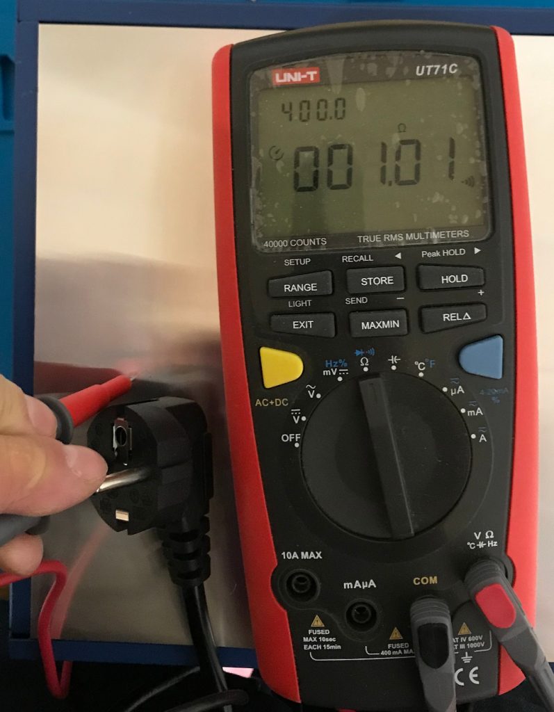
First step was to make sure that the solder plate is actually grounded properly.

ground check
1 Ohm is acceptable

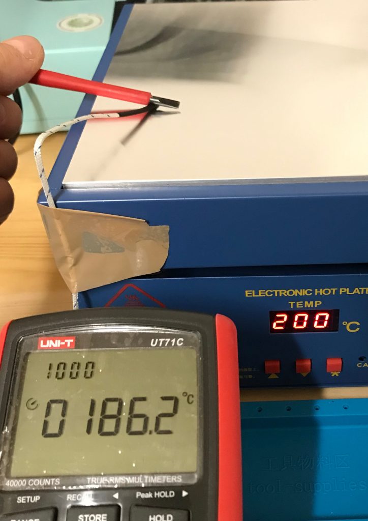
After that a layman’s temperature calibration run. Comparing the temperature using my multi-meter’s temperature probe and the internally measured value of the solder plate.

temp check
Close enough

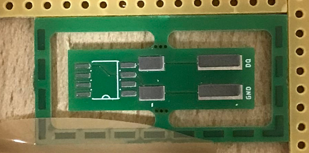
The PCBs were designed with eagle and manufactured by AISLER. They look good, were reasonably priced and came with a stencil.

On to solder paste application. The setup consists of a piece of wood with two pieces of PCB with the same thickness as the target PCB and the stencil taped in place after alignment. You can see in the image that the stencil is far from perfectly parallel to the hole line. The effect of slightly offsetting the solder paste will be visible soon.

setup
Solder paste application setup on a wooden board and a dry fit of the parts

Flipped the stencil over and put a drop of solder paste.

solder paste
Before application of the solder paste

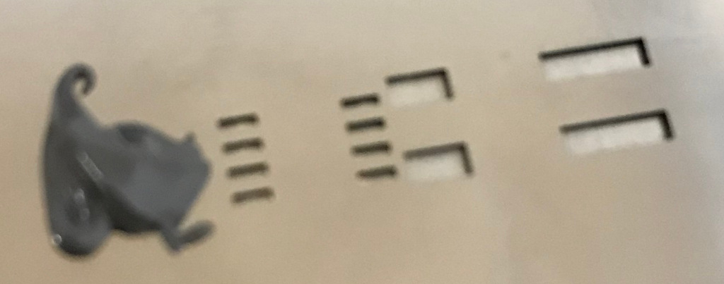
Using a metal scraper to apply.

solder paste applied
Solder paste applied.

The above mentioned error is visible, but I hope that it does not cause issues later and the amount of solder paste looks good. Next step is placing the parts.

parts placed
Using tweezers to place the parts

Now let’s heat it up. Since I’m using the solder plate for the first time I did not take enough pictures to capture the whole reflow solder profile. I’ve set the temperatures manually and have waited using a timer. The relatively slow solder plate ensures the ramping is not too fast. The cooling after reaching maximum heat is a little bit slow, but will be improved once I’ve the ventilation in place that is definitely required for larger projects. The fan is already in place, so I’ll have to add an enclosure only.

heated
Solder paste shortly after it started melting

Wait until it’s cooled.

soldered
The the solder joints look acceptable

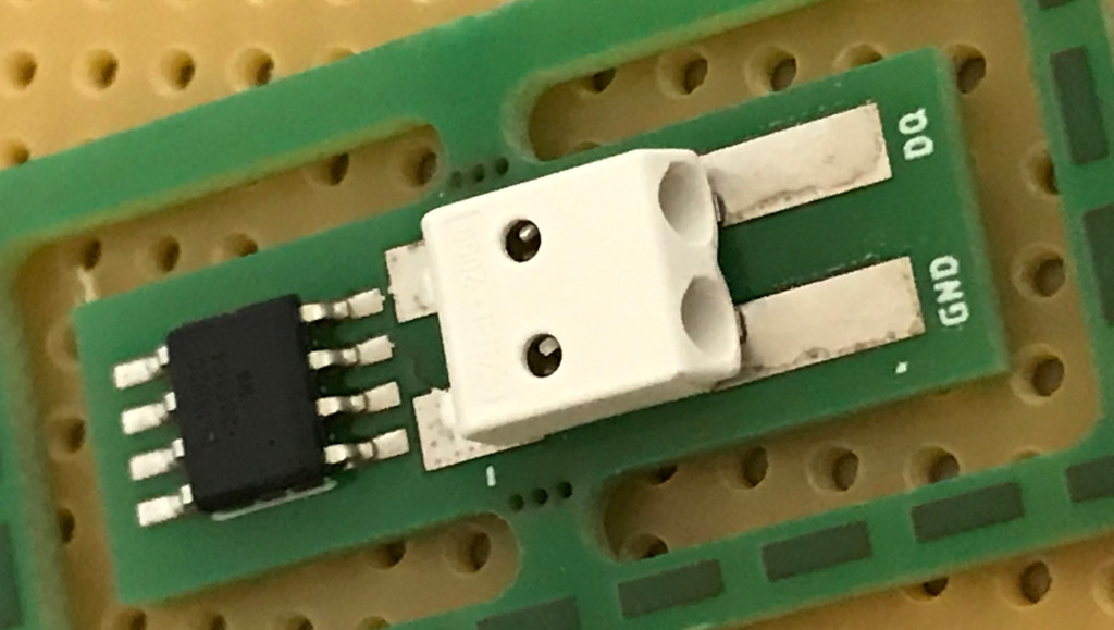
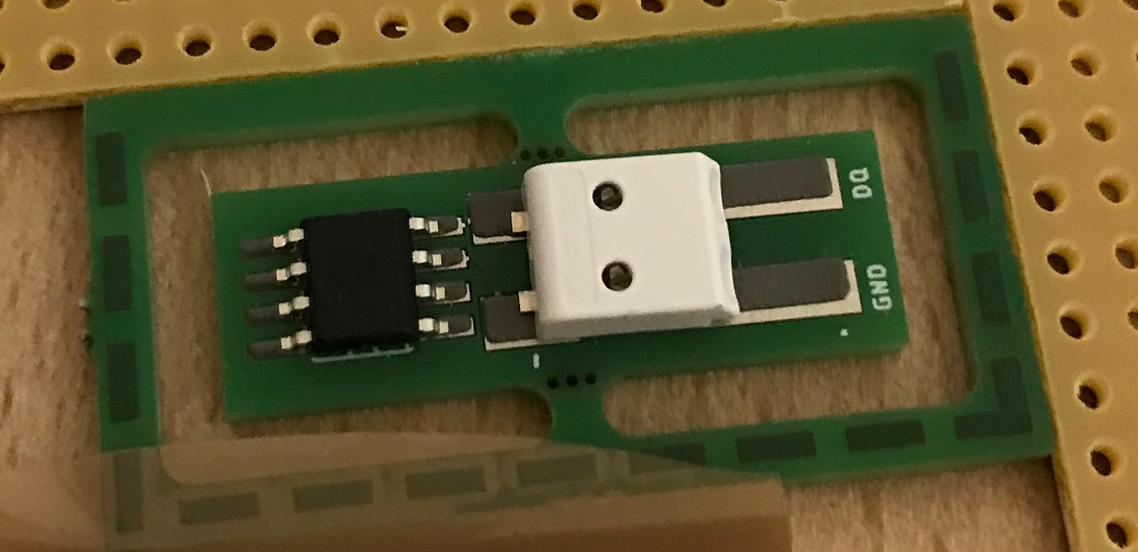
Considering the fact that the connector does not match 100% with the footprint (the 8D process will show what went wrong) the solder joint is acceptable. The temperature sensor looks good to me. (Feedback welcome). After the first one was successful I finished the series by soldering the remaining 2 parts.

mini series
The complete series of 3 parts is finished

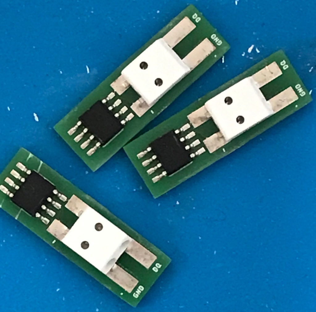
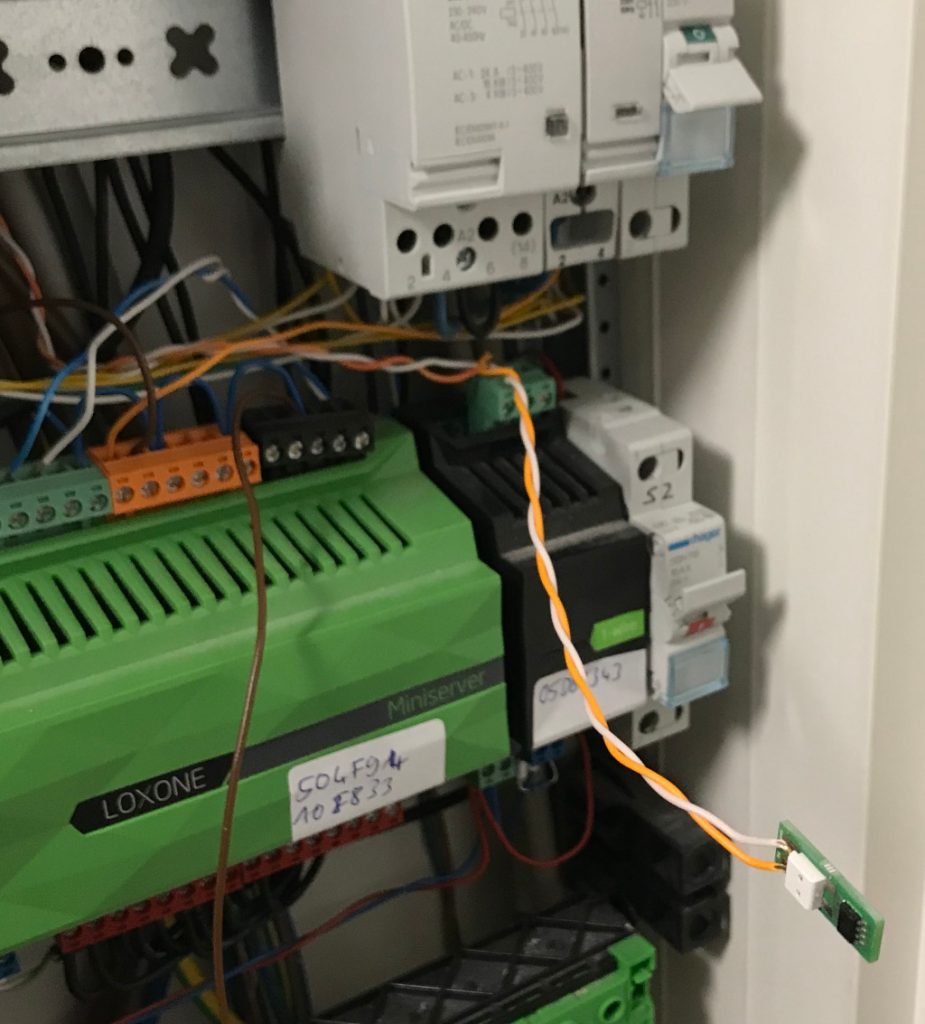
PCBs routed and sanded. I did a quick electrical test. With only 2 connections it could easily be done with the multi-meter. So the next step was to integrate the new sensor in the existing Loxone home automation system.

system test
The newly produced sensor is connected to the live system

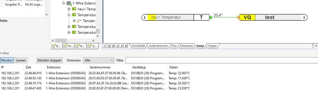
The sensor was successfully detected and provided a reasonable temperature.

GIU
The software displays a reasonable temperature value

In addition I’ve placed one of the sensors outside and it also show values that made sense.

I’ll order more PCBs and run a second batch and after that I’ll be out of excuses for producing the bigger PCBs for my light switches.

Home automation security

Of course loxone offers the possibility to connect the miniserver to the internet and also an app for mobile devices to connect to your smart home via internet. The problem is the connection is not as smart as expected. heise.de had a short and a long story about that.

So the first step is not to connect the system to the internet at all. The second step is to have a separate network for the home automation with very restricted access in both directions. Of course I want to use something like ntp ro make sure the time is always correct. But what I do not want is that the system is accessible from the outside.

Another reason to restrict the internet access for the miniserver is that after loxone provides a software update and the miniserver becomes “aware” it’ll start complaining that the software sould be updated. This is acceptable for the people who run the installation, but the normal user should not be bothered with that kind of information.

cancombase

With the help of Jonas as reviewer I’m one step closer to the solution that was missing in Switch selection. The first version of cancombase is finsihed.

The 5×10 cm pcb fits behind the switches in a double plug socket. The 4 pairs in the CAT cable will be used in the following way:

  1. Connect switch 1 to the miniserver and the backuo system (a post will follow)
  2. Power supply 24V (the selected switches need the 24V and I have decided – since I don’t know better – that a buck is easier than a boost)
  3. + 4. CAN (Since CAN bus does not allow a star topology it’ll be a long bus with a baud rate of around 100kBaud. Of course this has to be checked after installation. Wikipedia indicates that 125 kbit/s allow up to 500 meters of cable. A rough calculation )

A description of the PCB is available here. It’s based on the arduino pro mini. Or an available clone of it.

The gap between the now introduced CAN and the loxone miniserver will be filled (most probably) with a rasperry pi that converts the CAN messages to UDP messages the miniserver is able to read.

Apart from reading switch states (maybe with double-click detection) and writing to feedback LEDs the next version of cancombase will also contain a temperature sensor.

Switch selection

As mentioned before, I want a switch setup that is the same in every room. Of course I considered loxone touch connected to the miniserver by loxone tree  But I did not like it because of two reasons:

  1. The design is different from the design of the plugs and other elements. I don’t like the idea of having different looking electrical components.
  2. There is no possibility for a backup solution that allows to control light independent of the miniserver.

So I’ve chosen Taster 10 AX 250 V ~ (531 U)  (I’ll call it “1” from now on) and   Tastsensor-Modul 24 V AC/DC, 20 mA (A 5236 TSM) (I’ll call it “6” from now on, and the switch in the upper left will be called 6_1, the upper right 6_2 and so on …) from the company Jung.

The idea is to control the main light of each room with 1. 6_1 (up) and 6_2 (down) will be used for the roller blinds. The four remaining switches can be used differently in all rooms dependent on the needs.

But, and there’s always a but, a CAT cable only contains 8 wires. Even though it’d be enough for 7 push buttons there is no wire left for the 6 red feedback LEDs and the RGB LED. Connecting all that would require 3 CAT cables.

1 for 1
6 for 6_1 to 6_6
2 for Vcc and Ground
6 for red feedback LEDs
3 for RGB LED
----------
18 lines for each switch -> 3 CAT cables à 8 lines

That’s a price and effort I’m not willing to pay. It’d also mean that the miniserver has to provide 16 in/outputs for each room. This is what would make it really expensive. So I’ve decided to spend more of my time and come up with a solution that allows to connect my switch setup to the miniserver and to the backup circuitry at the same time while requiring only 1 CAT cable per switch.

Yes, that’s a cliffhanger.

Cables cables cables

Starting point of home automation is the signal and power cables routed to the switch cabinet in the basement. The additional cost and effort is the signal cables that would not be required in a traditional setup. The additional effort for the power lines can be neglected since the additional length from each room to the basement is compensated by less cable in the rooms for example from a switch for the roller blinds to the motor of the roller blind.

On the left you can see the power cables that go to the lights, plugs and roller blinds.

The red cables are the connections to the smoke detectors. Each room that is either a potential sleeping room or that is part of the escape path has a smoke detector (required by law). Additionally to the mandatory requirements they are connected on floor level and the floors are connected in the switch cabinet. In addition there is a connection between the three parts of the house. Currently they are all hard wired together. This might change in future to suppress the forwarding of alarms for some time. E.g. when testing smoke detectors in one part of the house it’s not desired to trigger all other smoke detectors.

As you can see there is still much space left in the switch cabinet, and that can’t be filled up only by simple fuses.

Nowadays, on floors that are partially constructed with wood, you’ve to install special fuses with spark detection . Those are 3 times the size of the traditional ones.

There will be the fault current protection switches that are nowadays mandatory for all three phases and not only for the bathroom.

There is my backup circuitry, that makes sure that, even without the home automation system, in each room the light can be switched and the roller blinds can be moved.

There will be a power supply for the backup system as well as for the home automation system.

And last but not least there will be the home automation system itself.

Logging data

Since the miniserver has only a SD-card as internal storage and it’s prone to wear I’m thinking about logging of data outside the miniserver. Loxone offers so called loggers. One possibility is to set the storage location to a syslog target outside the miniserver. so now the data is in /var/log/syslog of alix.

What I need next is a possibility to store the data over a long time and a possibility to display it.

Possibilities I see:

  1. Do everything on my own
  2. influx/grafana
  3. logstash/kibana

Since #1 means work and maintenance and #2 & #3 mean quite a big installation on a small system I’m very open to suggestions of something in between.

Home Automation

When building a house of course the question comes up whether, and immediately after that, how much home automation should be implemented. First step after deciding that I want home automation was the selection of a system. I decided to use loxone. There are reasons:

  1. One of my friends already has some experience with the system
  2. The system is centralized, so in case it has to be replaced it can be done in that central place and no hardware updates are required in the living room. The centralized solution also allows to set up a backup system that provides basic functionality like switching of light and opening/closing of roller blinds.
  3. The company delivers the configuration software with the hardware without additional costs and conditions. If I want to update anything in the future I can do that. If I want to stick with an old version of their software I can stick with that.

The home automation has the goal to be invisible for the user and offer all the functionality that you’re used to in a “normal” home as a base. If you enter a room there shall be a switch that will turn on the light if pressed. Only if you want to you can dim the light by holding the switch or by double clicking.

Also the basic setup should look the same in all the rooms. So I’ve decided for a combination of a normal sized light switch and a 6 pin switch below it.

Details will follow.

The mechanical part of the house already exists: