Now that the prototype is running it’s time to move on to “series” production. The files of the first version are here.
So a PCB has to be designed and the parts have to be selected and tested. Selecting the parts is not that difficult, but designing a PCB is not that easy since I don’t have any experience. In addition it looks like the old days are finally over. It’s becoming more and more difficult to get non-SMD-parts.
Btw: I’ve updated the pictures. The red background was a little bit too much and had to be changed to black.
Question: Does anybody have a good idea how to take picture to show that the dimming is working?
Tag: DMX
First Result
Yesterday evening the first real result was visible. Reception of DMX data and output of PWM on 8 channels is working now.
At the moment it’s only a development board.
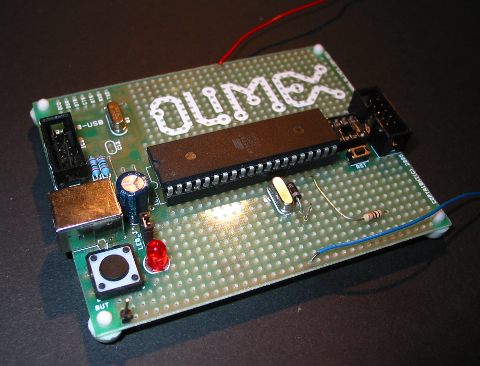
All external parts are attached via loooong cables to other hardware.
A PCB Design is ongoing, but not all the details are yet clear for series production.
OKOK, that was maybe a little bit to short. First of all:
DMX: a strange protocol, that looks like it was intended to keep amateurs from building their own devices by adding a protocol error as start signal. But with todays µCs is possible, even though it’s a little bit ugly.
In my setup there is a light control desk which is the sender. So I only care about receiving at the moment.
The received 8 byte are saved in the µC and are the input data for the PWM generator.
Th PWM signal is used for PFC.
An external circuitry is used to detect the zero crossing of the 230V AC and based on the received DMX data triacs can be started.
Now that the basic functionality is working I can add service functions and error detection.