I’ve been to Tours in France. For picking up my sister at the Euro Gusto. This is an exposition comparable to the Slow Food. OK, I’ve to admit it’s not very reasonable to drive 1800 km in 3 days just for having a look at some wine and tasting some smelling cheese. But I like France and it was definitely good to away from work for some days and I had the possibility to correct some of my prejudice about French people. They tried hard to understand my bad French and did not ask for every word I’ve pronounced in a wrong way and they even tried to talk German to me.

The picture shows the things I’ve bought there: cheese, calvados, almonds, fleur de sel and nougat.
Author: admin
next steps
Now that the prototype is running it’s time to move on to “series” production. The files of the first version are here.
So a PCB has to be designed and the parts have to be selected and tested. Selecting the parts is not that difficult, but designing a PCB is not that easy since I don’t have any experience. In addition it looks like the old days are finally over. It’s becoming more and more difficult to get non-SMD-parts.
Btw: I’ve updated the pictures. The red background was a little bit too much and had to be changed to black.
Question: Does anybody have a good idea how to take picture to show that the dimming is working?
First Result
Yesterday evening the first real result was visible. Reception of DMX data and output of PWM on 8 channels is working now.
At the moment it’s only a development board.
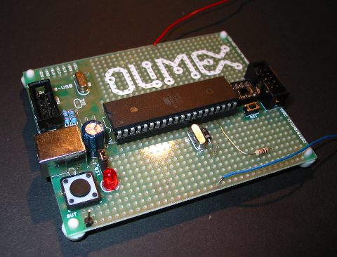
All external parts are attached via loooong cables to other hardware.
A PCB Design is ongoing, but not all the details are yet clear for series production.
OKOK, that was maybe a little bit to short. First of all:
DMX: a strange protocol, that looks like it was intended to keep amateurs from building their own devices by adding a protocol error as start signal. But with todays µCs is possible, even though it’s a little bit ugly.
In my setup there is a light control desk which is the sender. So I only care about receiving at the moment.
The received 8 byte are saved in the µC and are the input data for the PWM generator.
Th PWM signal is used for PFC.
An external circuitry is used to detect the zero crossing of the 230V AC and based on the received DMX data triacs can be started.
Now that the basic functionality is working I can add service functions and error detection.
USBprog
USPprog (available here) is a very useful tool. I mainly use it as a AVRISP mk2 clone. This is done by flashing an AVRISP mk2 emulation firmware in the µC of the USBprog. Tools for doing that are available for the command line and also as GUI. I’ve ordered the parts together with some ATMega32 µCs and a prototype board. Since the USBprog consists of very few parts it can be easily soldered even by not so experienced users. The result looks like this:
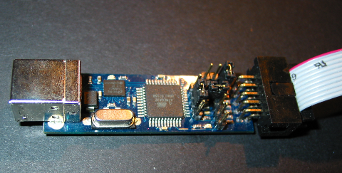
The difficult part is to flash the boot loader SW on it. It’s a chicken/egg problem. I want to flash a SW on a µC that I want to use for flashing a µC. But with an old PC that has a parallel port it can be done.
After that I had a working USBprog. On the right you can see the USB port and on the left the cable used to connect to the µC.
Justification
Having a complete PC is a good thing, but for controlling small things like a light it’s way too big and expensive, so I’ve decided to use smaller processors for that. After some research I ended up with the AVR micro controllers made by Atmel. They are easily available and affordabel and what is even more important: An open source toolchain consisting of avr-gcc and avr-libc exists and even the hardware I’ll be using for programming the µCs is open source: USBprog.
Hello world!
With some help of Alex this is now working and I can say “Hello world”
Whatever blogs were originally invented for, I’ll use it mainly as a documentation tool for my struggles with the atmega32.