cancombase

With the help of Jonas as reviewer I’m one step closer to the solution that was missing in Switch selection. The first version of cancombase is finsihed.

The 5×10 cm pcb fits behind the switches in a double plug socket. The 4 pairs in the CAT cable will be used in the following way:

  1. Connect switch 1 to the miniserver and the backuo system (a post will follow)
  2. Power supply 24V (the selected switches need the 24V and I have decided – since I don’t know better – that a buck is easier than a boost)
  3. + 4. CAN (Since CAN bus does not allow a star topology it’ll be a long bus with a baud rate of around 100kBaud. Of course this has to be checked after installation. Wikipedia indicates that 125 kbit/s allow up to 500 meters of cable. A rough calculation )

A description of the PCB is available here. It’s based on the arduino pro mini. Or an available clone of it.

The gap between the now introduced CAN and the loxone miniserver will be filled (most probably) with a rasperry pi that converts the CAN messages to UDP messages the miniserver is able to read.

Apart from reading switch states (maybe with double-click detection) and writing to feedback LEDs the next version of cancombase will also contain a temperature sensor.
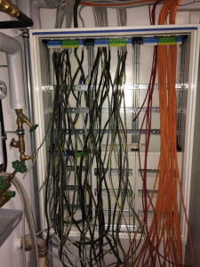
Cables cables cables

Starting point of home automation is the signal and power cables routed to the switch cabinet in the basement. The additional cost and effort is the signal cables that would not be required in a traditional setup. The additional effort for the power lines can be neglected since the additional length from each room to the basement is compensated by less cable in the rooms for example from a switch for the roller blinds to the motor of the roller blind.

On the left you can see the power cables that go to the lights, plugs and roller blinds.

The red cables are the connections to the smoke detectors. Each room that is either a potential sleeping room or that is part of the escape path has a smoke detector (required by law). Additionally to the mandatory requirements they are connected on floor level and the floors are connected in the switch cabinet. In addition there is a connection between the three parts of the house. Currently they are all hard wired together. This might change in future to suppress the forwarding of alarms for some time. E.g. when testing smoke detectors in one part of the house it’s not desired to trigger all other smoke detectors.

As you can see there is still much space left in the switch cabinet, and that can’t be filled up only by simple fuses.

Nowadays, on floors that are partially constructed with wood, you’ve to install special fuses with spark detection . Those are 3 times the size of the traditional ones.

There will be theĀ fault current protection switches that are nowadays mandatory for all three phases and not only for the bathroom.

There is my backup circuitry, that makes sure that, even without the home automation system, in each room the light can be switched and the roller blinds can be moved.

There will be a power supply for the backup system as well as for the home automation system.

And last but not least there will be the home automation system itself.