Second batch

After creating the first few temperature sensors the PCB has been updated. It’s smaller now. Soldering went smoothly. The fact that the PCBs came in groups of 6 made applying the solder paste much faster. After soldering the PCBs did not look very nice. But after measuring all were as expected and the question is whether to clean the PCBs would help to make sure the the remaining dirt does not cause long term problems. Unfortunately an off by one issue appeared.

Blink

I’ve connected the Arduino pro mini (328/5V) to my pcb. Of course it’s not directly soldered to the PCB but using a connector, so I can replace the parts that get bricked during development. I’ve downloaded the blink example using something like this. Directly after flashing it worked, but once I disconnected the flashing adapter it stopped. After remembering, that I’ve to short my optional filter in case it’s not assemble it works.

unfortunately…

… an ohmic load (Thank you Axel) shows the same behavior (spikes on Vout) as seen in the previous post. Fortunately I’ve spent some space on the pcb for an optional filter that has now become mandatory.

The spikes do not change with load or input voltage. I took a closer look and they are much less random compared to what the screenshot looks like. They’re expected transient responses to the switching. currently they’re around +- 1,5V which is too much.

Unfortunately the additional inductor and capacitor for the filter where not part of the part delivery I’ve received. The delivery date is changing once a week and is oscillating around 30th of march.

But in the meantime I still can try to get the arduino running. It has it’s own voltage regulator and an additional capacitor at the input, so the currently “dirty” Vout will not be an issue.

Load

I’ve run the power supply under load. As you can see I’ve

  1. not yet removed the screen protector foil from my multimeter
  2. connected the cables in the wrong direction so the current is negative
load current @ Vout=5V [A]

The load was a florist wire that accidentally had the correct length to have a resistance of 10 Ohm (Just in case: R=U/I). So in addition to the resistance it also is an inductive load due to the geometric nature of florist wire.I did not want to unwind it.

Channel 1: Vout
Channel 2: buck inductor input voltage

Three things can be seen:

  1. I’ve a problem with reflections and need a better environment for taking pictures (or an oscilloscope with screen shot functionality)
  2. The switching frequency of around 122kHz can be seen on the buck inductance. (Channel 2)
  3. There are spikes on Vout (Channel 1). They correlate with the switching points of the buck and are most probably caused by the “coily” nature of my florist wire load.

The result of the short test is that I’ve not noticed heating on the pcb or the parts even though I’m running the circuitry at the upper boundary of what it’s designed for. That’s good. For a real test with reasonably long duration (> 1 day) I need a fire proof environment, that also contains the designated housing, so that air turbulence can not cool down the pcb and of course a possibility to measure and log the temperature over time.

Power!

After a (luckily unsuccessful) search for short cuts I have connected the power supply part on the pcb to an external power supply. The following screen shot shows that the power supply becomes operational at around 12V.

Channel 1: Vout
Channel 2: Vin (manual rise from 0 to 15V )

Unfortunately I do not have a nice load to check the behavior close to the 0,5A the power supply is designed for. But I have small light bulb that causes a load of around 30 mA. Running the power supply at this load for some minutes did not cause any noticeable increase of the temperature. That’s a good sign. I also tried a short cut between Vout and GND. Nothing bad happened. The MAX5033 detected the short cut and shut off, before trying to start again. After removing the short cut it went back to normal. This state I did not try for a longer time. The effects were visible on the oscilloscope and audible. Typically the inductors start to “sing” under such conditions.

My external power supply can only provide 20V, but I assume, that if everything works at 20V it’ll also run at 24V. So the next step before actually connecting the arduino is to run the power supply for an extended period of time (~ 1 day) with high load and 24V input.

An attempt on soldering

After a long time I’ve reactivated my solder iron. Since I’ve done that without additional flux (apart from the content of the solder) the result looks accordingly. My next step will be testing the circuitry.

power supply part of the cancombase

Surprisingly for me the soldering of the IC was the easiest. I assume, that the pads were perfectly sized for hand soldering. The resistors and small capacitors look horrible because I did not use tweezers. The large capacitor’s solder pads are a bit too small for hand soldering and the inductor needs a higher temperature because of the relatively high mass.

I also noticed that I’ve to improve my documentation. More information on the pcb, the layout and the circuit diagrams are required to simplify the soldering and reduce the time spent on searching the parts and their orientation. For example having the small dot that indicates pin 1 of an IC would be very helpful. Also the orientation of the larger capacitors and the exact location and size of the text on the pcb.

Prototype

After ordering the prototype pcbs in China on Saturay they arrived on the following Wednesday. I even got one more pcb than I’ve ordered. The service is very fast and the price more than acceptable. So based on this single sample I can recommend allpcb.com. Apart from the silkscreen, the pcb looks good. But I’ve put exactly zero effort in it, so it’s OK. The picture shows the Arduino pro mini plugged in, but not yet soldered.

prototype pcb with loosly mounted arduino pro mini

The next step is to solder the power supply parts (visible here on the very right) and the optional filter against ripple. After that the difficult part, soldering the oscillator, will be the next step.

Home automation security

Of course loxone offers the possibility to connect the miniserver to the internet and also an app for mobile devices to connect to your smart home via internet. The problem is the connection is not as smart as expected. heise.de had a short and a long story about that.

So the first step is not to connect the system to the internet at all. The second step is to have a separate network for the home automation with very restricted access in both directions. Of course I want to use something like ntp ro make sure the time is always correct. But what I do not want is that the system is accessible from the outside.

Another reason to restrict the internet access for the miniserver is that after loxone provides a software update and the miniserver becomes “aware” it’ll start complaining that the software sould be updated. This is acceptable for the people who run the installation, but the normal user should not be bothered with that kind of information.

cancombase

With the help of Jonas as reviewer I’m one step closer to the solution that was missing in Switch selection. The first version of cancombase is finsihed.

The 5×10 cm pcb fits behind the switches in a double plug socket. The 4 pairs in the CAT cable will be used in the following way:

  1. Connect switch 1 to the miniserver and the backuo system (a post will follow)
  2. Power supply 24V (the selected switches need the 24V and I have decided – since I don’t know better – that a buck is easier than a boost)
  3. + 4. CAN (Since CAN bus does not allow a star topology it’ll be a long bus with a baud rate of around 100kBaud. Of course this has to be checked after installation. Wikipedia indicates that 125 kbit/s allow up to 500 meters of cable. A rough calculation )

A description of the PCB is available here. It’s based on the arduino pro mini. Or an available clone of it.

The gap between the now introduced CAN and the loxone miniserver will be filled (most probably) with a rasperry pi that converts the CAN messages to UDP messages the miniserver is able to read.

Apart from reading switch states (maybe with double-click detection) and writing to feedback LEDs the next version of cancombase will also contain a temperature sensor.

Switch selection

As mentioned before, I want a switch setup that is the same in every room. Of course I considered loxone touch connected to the miniserver by loxone tree  But I did not like it because of two reasons:

  1. The design is different from the design of the plugs and other elements. I don’t like the idea of having different looking electrical components.
  2. There is no possibility for a backup solution that allows to control light independent of the miniserver.

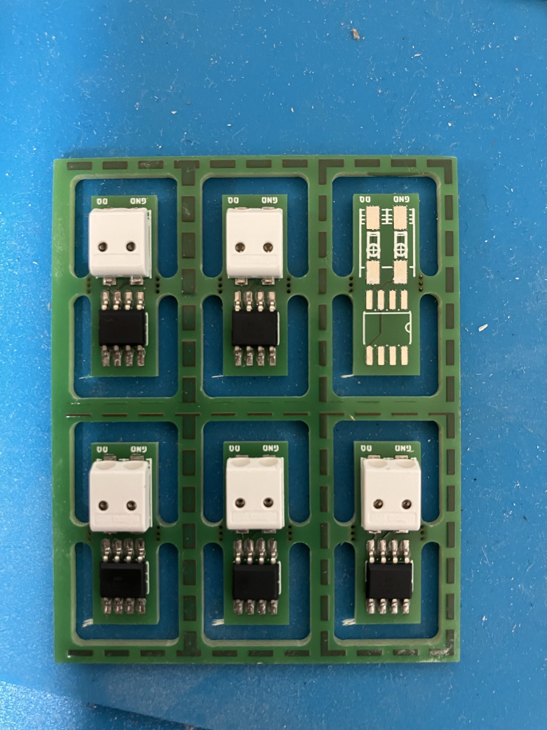
So I’ve chosen Taster 10 AX 250 V ~ (531 U)  (I’ll call it “1” from now on) and   Tastsensor-Modul 24 V AC/DC, 20 mA (A 5236 TSM) (I’ll call it “6” from now on, and the switch in the upper left will be called 6_1, the upper right 6_2 and so on …) from the company Jung.

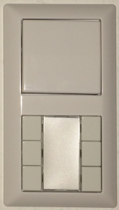
The idea is to control the main light of each room with 1. 6_1 (up) and 6_2 (down) will be used for the roller blinds. The four remaining switches can be used differently in all rooms dependent on the needs.

But, and there’s always a but, a CAT cable only contains 8 wires. Even though it’d be enough for 7 push buttons there is no wire left for the 6 red feedback LEDs and the RGB LED. Connecting all that would require 3 CAT cables.

1 for 1
6 for 6_1 to 6_6
2 for Vcc and Ground
6 for red feedback LEDs
3 for RGB LED
----------
18 lines for each switch -> 3 CAT cables à 8 lines

That’s a price and effort I’m not willing to pay. It’d also mean that the miniserver has to provide 16 in/outputs for each room. This is what would make it really expensive. So I’ve decided to spend more of my time and come up with a solution that allows to connect my switch setup to the miniserver and to the backup circuitry at the same time while requiring only 1 CAT cable per switch.

Yes, that’s a cliffhanger.