I’ve run the power supply under load. As you can see I’ve
- not yet removed the screen protector foil from my multimeter
- connected the cables in the wrong direction so the current is negative
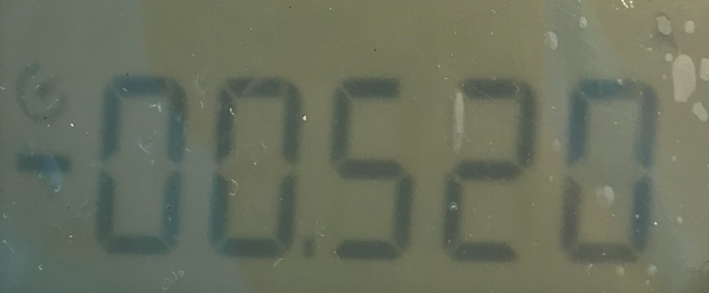
The load was a florist wire that accidentally had the correct length to have a resistance of 10 Ohm (Just in case: R=U/I). So in addition to the resistance it also is an inductive load due to the geometric nature of florist wire.I did not want to unwind it.
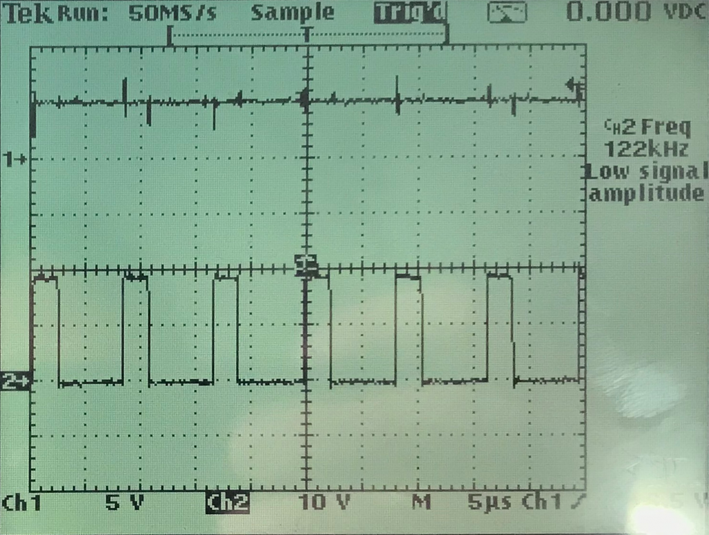
Channel 2: buck inductor input voltage
Three things can be seen:
- I’ve a problem with reflections and need a better environment for taking pictures (or an oscilloscope with screen shot functionality)
- The switching frequency of around 122kHz can be seen on the buck inductance. (Channel 2)
- There are spikes on Vout (Channel 1). They correlate with the switching points of the buck and are most probably caused by the “coily” nature of my florist wire load.
The result of the short test is that I’ve not noticed heating on the pcb or the parts even though I’m running the circuitry at the upper boundary of what it’s designed for. That’s good. For a real test with reasonably long duration (> 1 day) I need a fire proof environment, that also contains the designated housing, so that air turbulence can not cool down the pcb and of course a possibility to measure and log the temperature over time.