After a (luckily unsuccessful) search for short cuts I have connected the power supply part on the pcb to an external power supply. The following screen shot shows that the power supply becomes operational at around 12V.
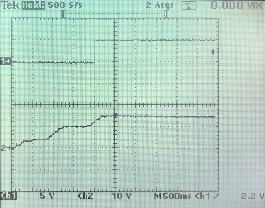
Channel 2: Vin (manual rise from 0 to 15V )
Unfortunately I do not have a nice load to check the behavior close to the 0,5A the power supply is designed for. But I have small light bulb that causes a load of around 30 mA. Running the power supply at this load for some minutes did not cause any noticeable increase of the temperature. That’s a good sign. I also tried a short cut between Vout and GND. Nothing bad happened. The MAX5033 detected the short cut and shut off, before trying to start again. After removing the short cut it went back to normal. This state I did not try for a longer time. The effects were visible on the oscilloscope and audible. Typically the inductors start to “sing” under such conditions.
My external power supply can only provide 20V, but I assume, that if everything works at 20V it’ll also run at 24V. So the next step before actually connecting the arduino is to run the power supply for an extended period of time (~ 1 day) with high load and 24V input.